SODAQ SARA SFF (Small Form Factor)

Overview
The SODAQ Small Form Factor (SFF) is the SODAQ SARA in a small package.
| Module | Technology | Shop |
|---|---|---|
| N211 | NB-IoT | SODAQ SARA SFF N211 |
| N310 | NB-IoT 2nd Gen | SODAQ SARA SFF N310 |
| R410 | NB-IoT, LTE-M | SODAQ SARA SFF R410 |
| R412 | NB-IoT, LTE-M, 2G | SODAQ SARA SFF R412 |
| G350 | 2G | |
| U201 | 3G |
Getting Started
Follow the getting started guide to verify you use the correct URL and update your boardfiles to the latest version.
Features
| Microcontroller | ATSAMD21G18, 32-Bit ARM Cortex M0+ |
| Compatibility | Arduino M0 Compatible |
| Size | 50 x 25.4mm |
| Operating Voltage | 3.3V |
| I/O Pins | 14 |
| Analog Output Pin | 10-bit DAC |
| External Interrupts | Available on all pins* |
| DC Current per I/O pin | 7 mA |
| Flash Memory | 256 KB |
| SRAM | 32KB |
| EEPROM | Up to 16KB by emulation |
| Clock Speed | 48 MHz |
| Power | 5V USB power and/or 3.7 LiPo battery |
| Charging | Solar charge controller, up to 500mA charge current |
| LED | RGB LED |
| NB-IoT | uBlox SARA N2XX, N3XX, R4XX Series |
| LTE-M | uBlox SARA R4XX Series |
| 2G/GPRS | uBlox SARA R412M |
| GPS/GNSS | uBlox EVA 8M/M8M |
| Accelerometer/Magneto | LSM303AGR |
| USB | MicroUSB Port |
Note
It's not recommended to use pin D8 for an external interrupt, pin D8 is attached to EXTERNAL_INT_NMI
Pinout
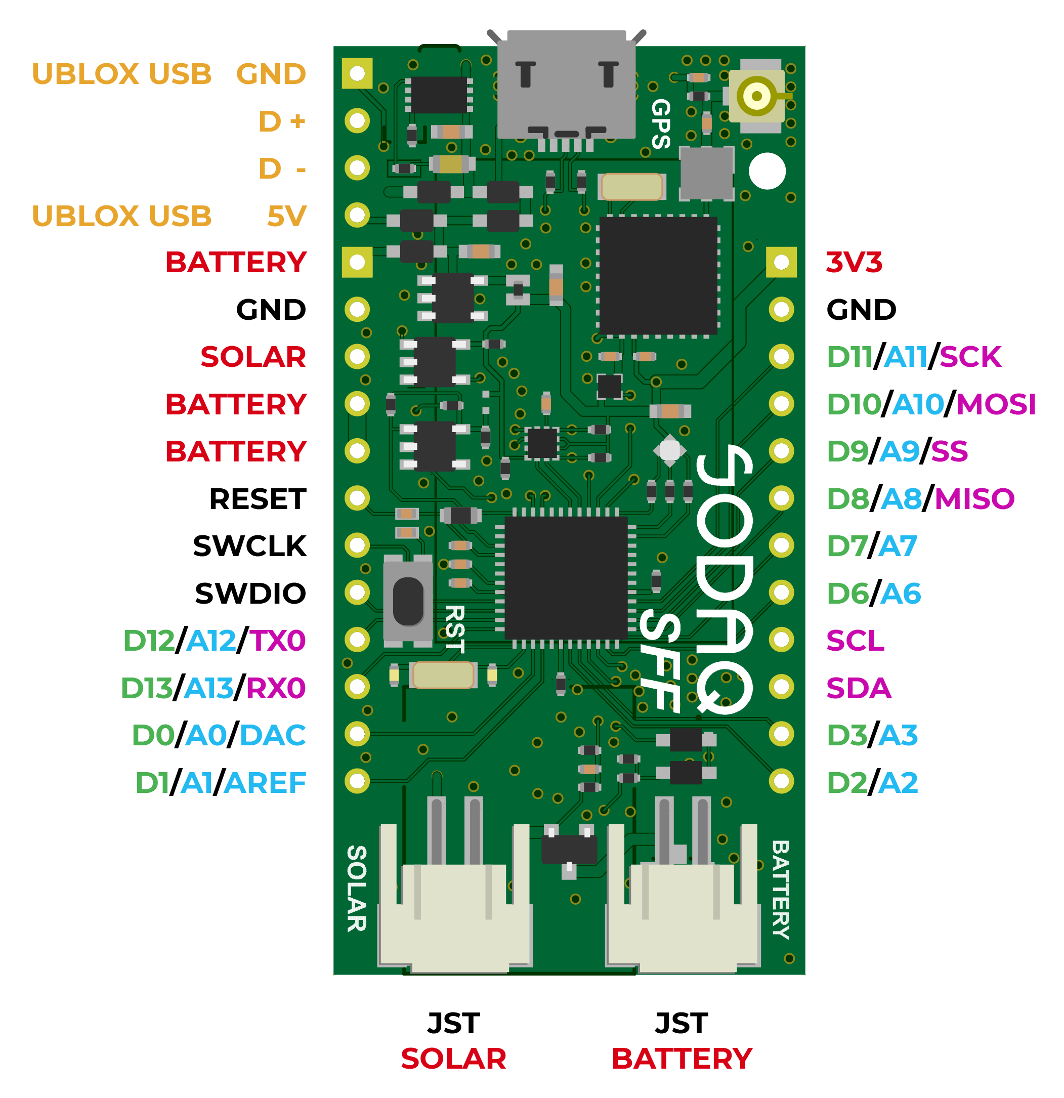
Note
The first four pins are to update the ublox module
The ublox GND, D+, D- and 5V are only for the R4XX modules.
The N2XX series don't have these pins connected, you can update via the passthrough.
The N3XX don't have a USB pinout, they have UART pinout.
The N3XX pinout will be added later when we also update the update process for this module.
Pin definitions
Some things like the onboard LED and the RGB LED are used on multiple boards. To make it more easy you can use the definition name.
Example:
pinMode(13, OUTPUT) and pinMode(LED_BUILTIN, OUTPUT) will do the same.
| Pin description | Pin number | Definition |
|---|---|---|
| Red LED | D17 | LED_RED |
| Green LED | D19 | LED_GREEN |
| Blue LED | D14 | LED_BLUE |
| GPS Enable | D18 | GPS_ENABLE |
| GPS Timepulse | D21 | GPS_TIMEPULSE |
| Power Pin SARA | D49 | SARA_ENABLE |
| Power Enable Pin SARA | D51 | SARA_TX_ENABLE |
| Change voltage pin SARA (3.3V – 1.8V) | D15 | SARA_R4XX_TOGGLE |
| Status Pin SARA | D52 | SARA_STATUS |
| MISO (SPI) | D8 | MISO |
| SS (SPI) | D9 | SS |
| MOSI (SPI) | D10 | MOSI |
| SCK (SPI) | D11 | SCK |
| Accelerometer Interrupt 1 | D5 | ACCEL_INT1 |
| Accelerometer Interrupt 2 | D4 | ACCEL_INT2 |
| Magnetometer Interrupt | D50 | MAG_INT |
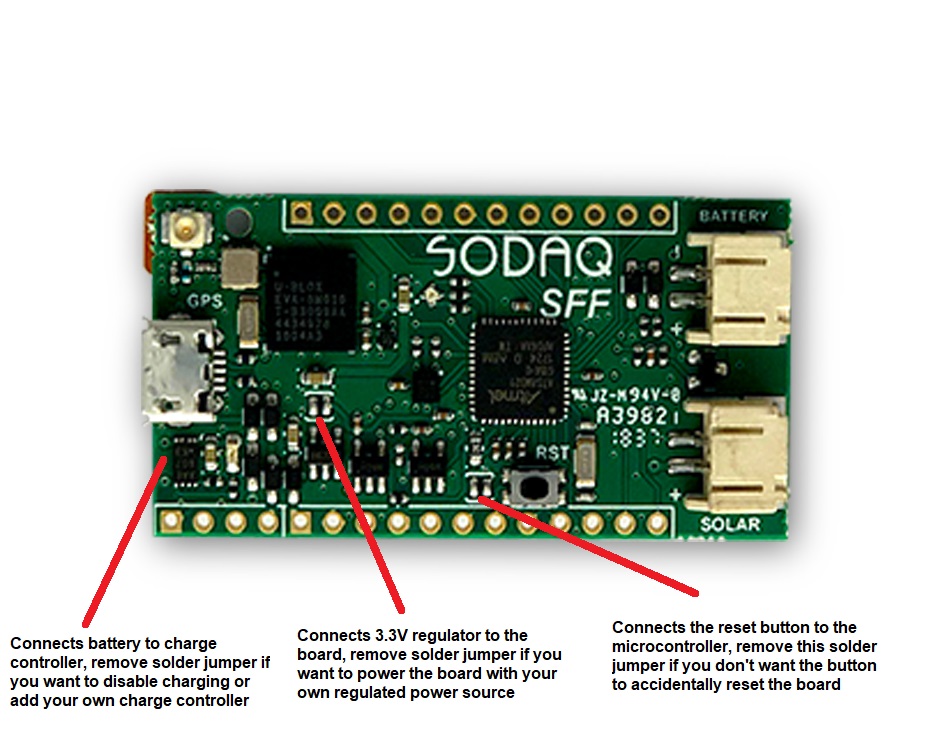
Solderjumpers
Schematics
Firmware Upgrade
Contact your u-blox representive to obtain the latest firmware.
R4
With the command ATI9 you can check your firmware version.
The latest firmware version for the R412 is M0.12.00,A.02.19.
The latest firmware version for the R410 is L0.0.00.00.05.12,A.02.19.
Note
From these firmware versions it's required to set a MNO Profile.
Note
The firmware update tool is only available for Windows.
- Install EasyFlash.
- Move the installation file to the EasyFlash installation folder.
- Reboot your PC.
-
Solder on a USB cable to the four SARA USB pins to connect a USB cable directly to the ublox module.
SARA SFF Rev.1
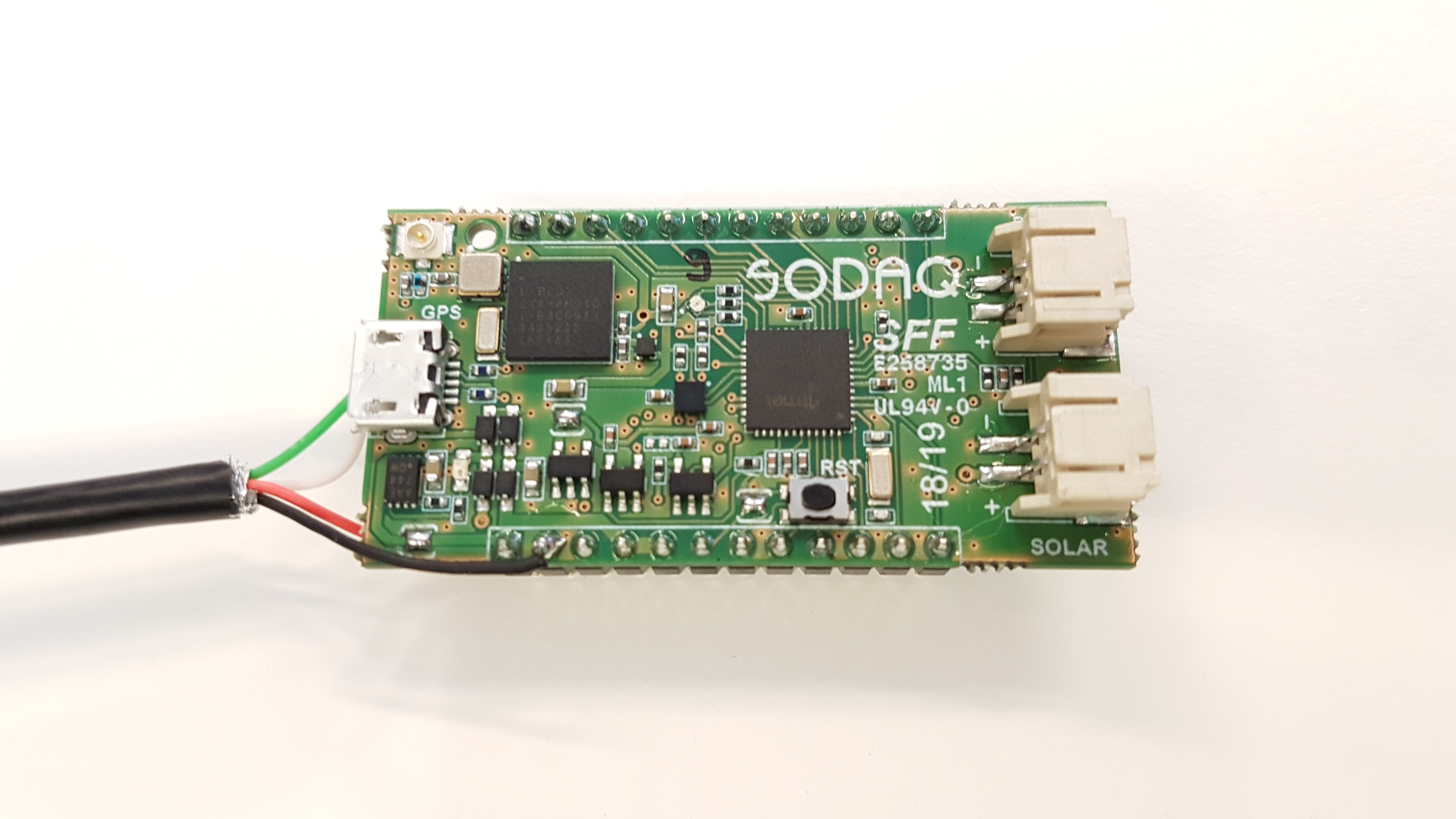
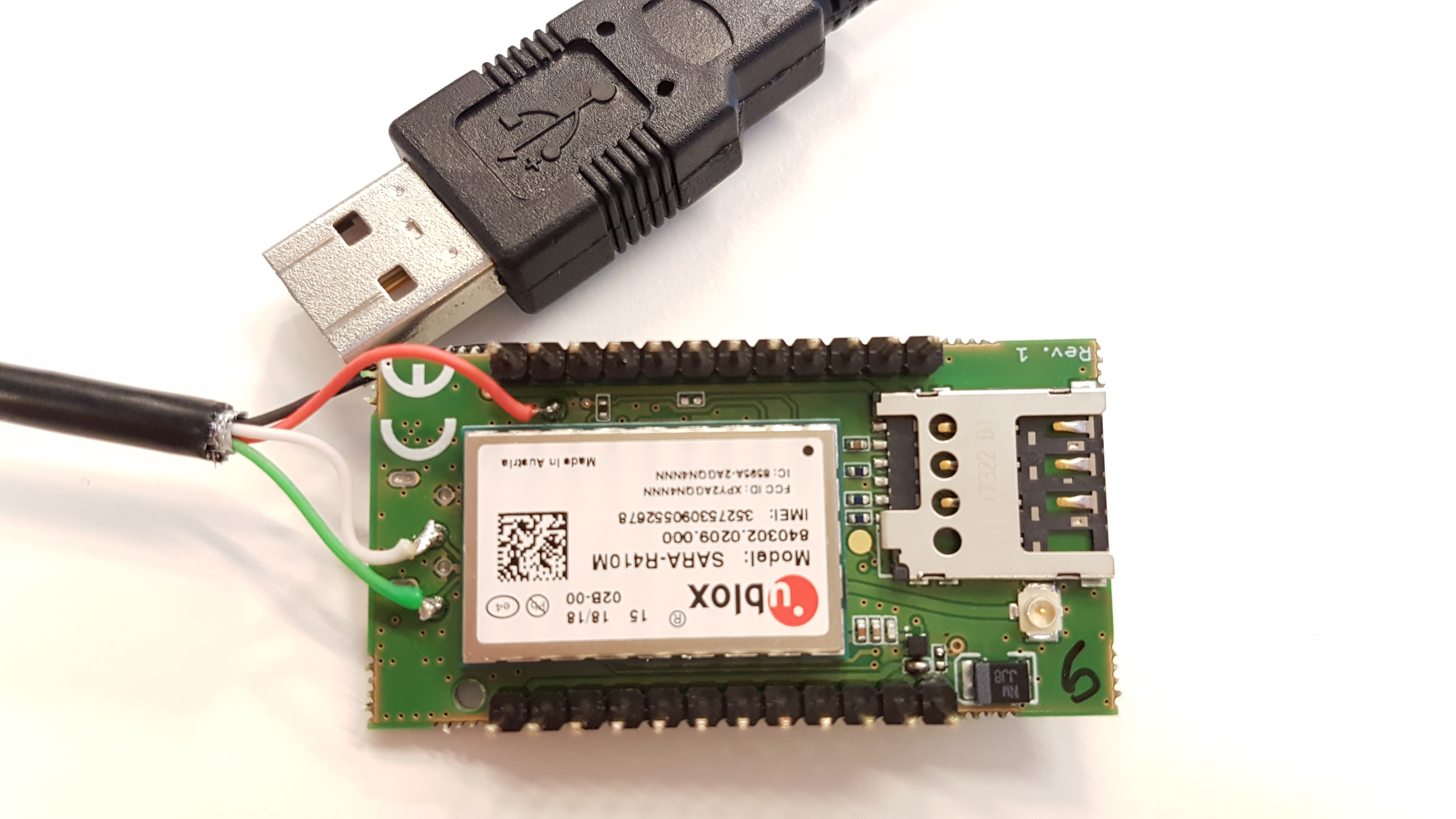
SARA SFF Rev.2
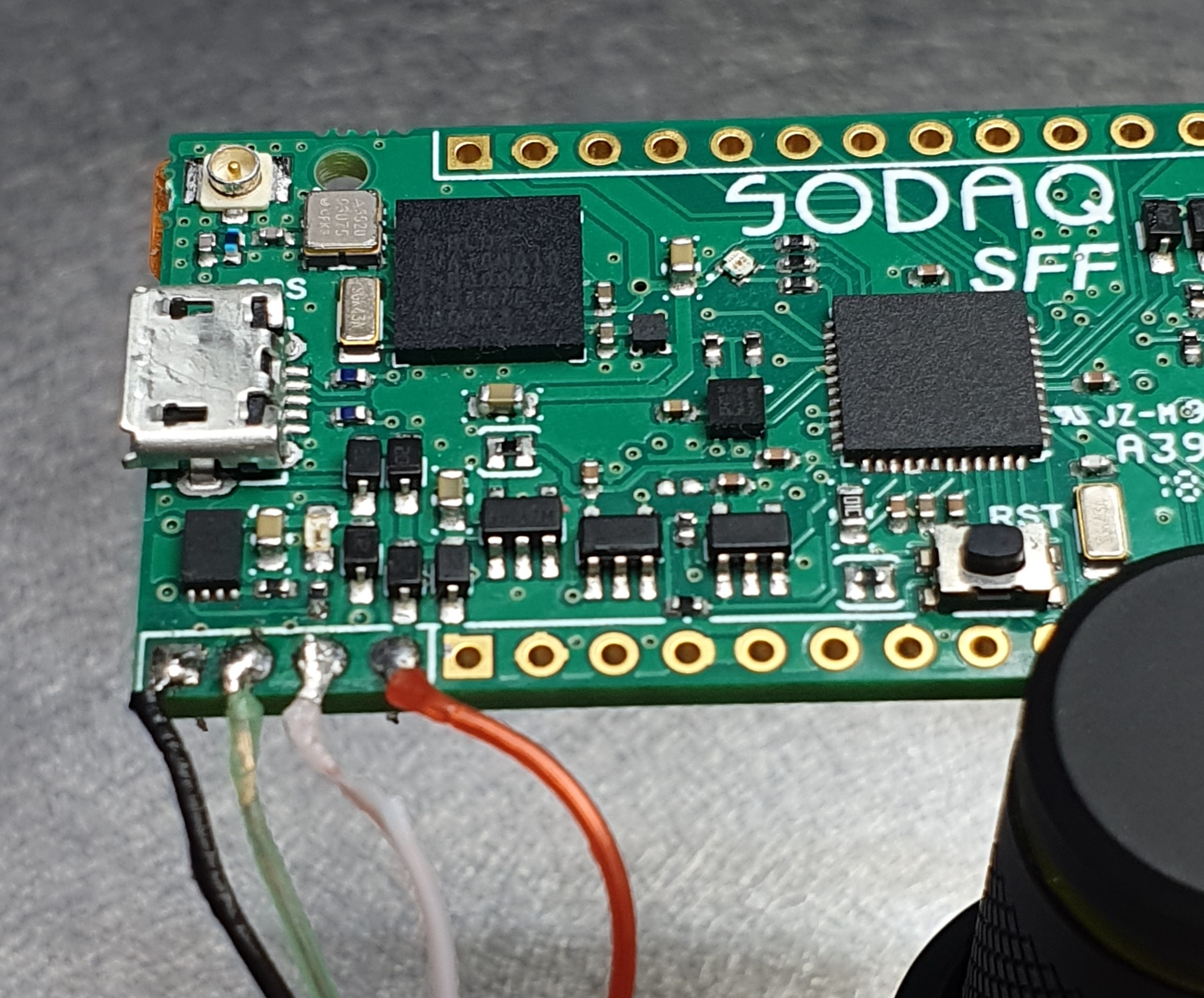
Pin Color Function 1 Black GND 2 Green USB + 3 White USB - 4 Red Vcc Note
The colors inside a USB cable can be different then in the picture above.
When you get the notification: USB not recognized, switch the USB- and USB+ cables. -
Use the regular USB port to load the passthrough sketch.
- Connect the 2nd (manually soldered) USB to your PC.
- Open EasyFLash as administrator.
- Select the correct module, select USB, leave the 3rd option blank.
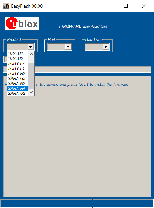
- Hit Update, wait till completion and have fun exploring the new features!
N2
With the command ATI9 you can check your firware version. Result N2 should be: 06.57,A10.08
Note
The N2 modules need to be updated to 06.57,A07.03 before updating to 06.57,A09.06.
The N2 modules need to be updated to 06.57,A09.06 before updating to 06.57,A10.08.
- Load the passthrough sketch on your board.
- Open UEUpdater.
- Select the correct firmware file.
- Press the Update button and wait for 60 seconds.
- The program tells you the update is complete.
- Your module is updated!
N3
With the command ATI9 you can check your firware version. Result N3 should be: 18.13,A01.01
-
Load the passthrough.
-
Check if your modules isn't in power saving mode.
You can do this withAT+NVSETPM?. The result should be 0.
If the result isn't 0, you need to set it and reboot.
Disable withAT+NVSETPM=0then rebootAT+CFUN=16. -
Disconnect the USB.
-
Connect the 2nd UART pins via a USB to Serial converter.
Pin SFF USB to Serial board 1 GND * GND 2 D + * TX 3 D - * RX 4 5 V * 3.3V
*Pinout based on the pinout picture on the SFF support page.
Actual pinout is GND, RX, TX, VCC