ExpLoRer

Overview
This is the ExpLoRer board that we designed for Microchip.
| Intended use | The ExpLoRer is a development/evaluation tool intended for the evaluation of Microchip wireless modules in a Research and Development laboratory environment. It is not a Finished Appliance. Manufacturers who integrate ExpLoRer in a Finished Appliance product must take responsibility to follow regulatory guidelines, for example for CE marking. |
| Warning | Do not short circuit the Li-Ion coin cell or any of the pins of the ExpLoRer because of risk of heat, smoke, and fire. |
| Warning | Take appropriate precautions while handling the PCB assembly because of exposed components. |
| Warning | Do not ship the Li-Ion coin cell outside the battery holder. |
| Warning | Do not alter the device into regulatory non-compliant modes. |
Getting Started
Follow the getting started guide to verify you use the correct URL and update your boardfiles to the latest version.
Features
| Microcontroller | ATSAMD21J18, 32-Bit ARM Cortex M0+ |
| Compatibility | Arduino M0 Compatible |
| Size | 93 x 55 mm |
| Operating Voltage | 3.3V |
| I/O Pins | 20 |
| Analog Output Pin | 10-bit DAC |
| External Interrupts | Available on all pins |
| DC Current per I/O pin | 7 mA |
| Flash Memory | 256 KB and 4MB (external flash) |
| SRAM | 32KB |
| EEPROM | Up to 16KB by emulation |
| Clock Speed | 48 MHz |
| Power | 5V USB power and/or 3.7 LiPo battery |
| Charging | Solar charge controller, up to 500mA charge current |
| LED | RGB LED, Blue LED |
| LoRa | Microchip RN2483 Module |
| Bluetooth | Microchip RN4871 Module |
| Cyptochip | ATECC508A |
| Temperature sensor | MCP9700AT |
| USB | MicroUSB Port |
| Coin cell holder | LIR2450. 3.6V |
Pinout
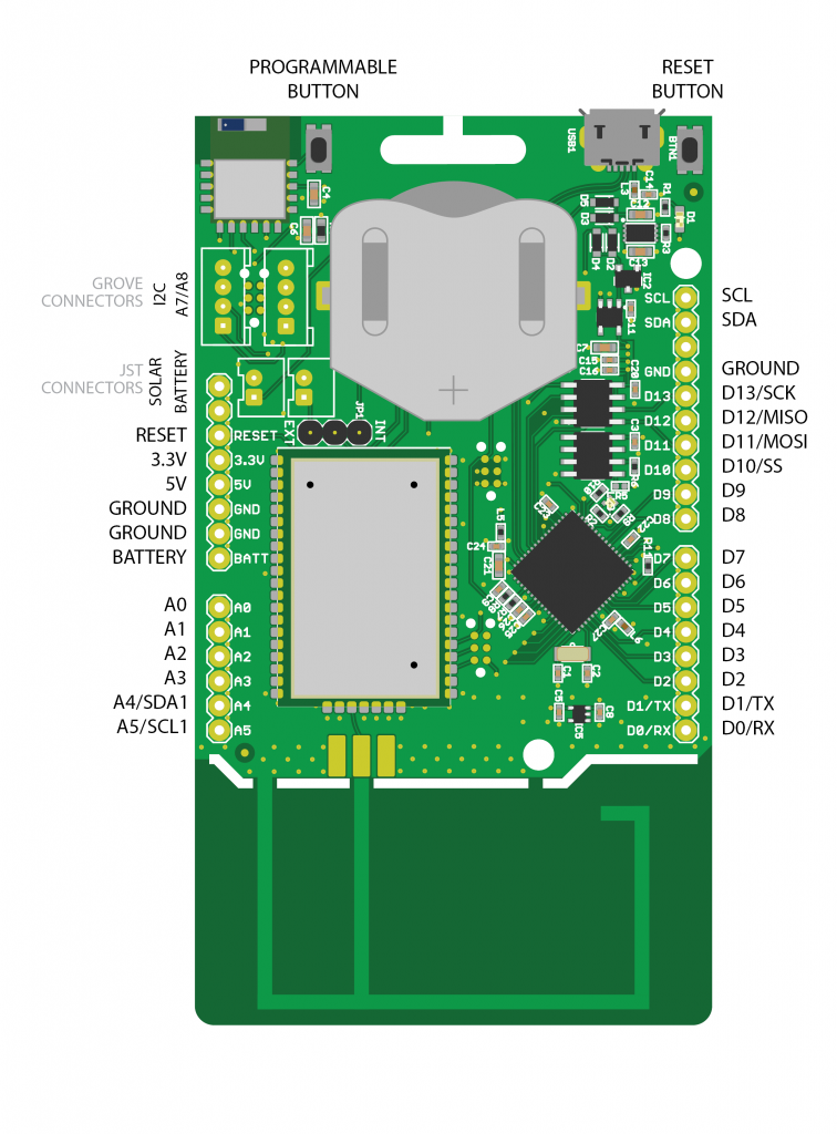
The 5V pin will pass-through the incoming voltage from the USB.
This means that on a battery powered solution the 5V will not be available.
Tag connect headers
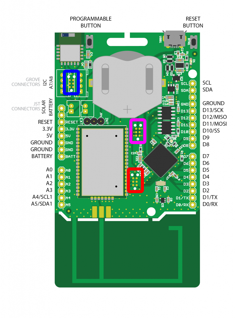
Blue : Bluetooth
Red : LoRa
Pink : MCU
Pin definitions
Now that you’re using the SODAQ ExpLoRer board files, you’ll be able to use our handy pin definitions. Our pin definitions allow you to address by name instead of pin number.
Here are all the pin definitions for the SODAQ ExpLoRer:
| Pin description | Pin number | Definition |
|---|---|---|
| RGB Red LED | D16 | LED_RED |
| RGB Green LED | D17 | LED_GREEN |
| RGB Blue LED | D18 | LED_BLUE |
| Blue LED | D13 | LED_BUILTIN |
| Bluetooth Wake | D19 | BLUETOOTH_WAKE |
| Bluetooth Reset* | BT_RESET | |
| Push Button* | BUTTON | |
| LoRa Reset* | LORA_RESET | |
| Temperature Sensor | A6 | TEMP_SENSOR |
| MISO (SPI) | D12 | MISO |
| SS (SPI) | D10 | SS |
| MOSI (SPI) | D11 | MOSI |
| SCK (SPI) | D13 | SCK |
*Rev5 and higher
PWM Pins
PWM can be used on D8, D10, D11, D12, D13, D14(A7), D15(A8), D16(LED_RED), D17(LED_GREEN) and D18(LED_BLUE).
Grove
The Grove connector on the outside of the board can be used for I2C.
The Grove connector on the inside of the board can be used as A7/A8 or D14/D15.
Hardware Serials
The SODAQ ExpLoRer has 4 hardware serials:
SerialUSB – This is for when you are debugging over the USB Cable.
Serial – Serial is attached to pin D1/TX and D0/RX.
Serial1 – Is connected to the Bluetooth Module.
Serial2 – Is connected to the RN2XX3 LoRaWAN Module.
void setup() {
  // put your setup code here, to run once:
  SerialUSB.begin(57600);
  Serial.begin(57600);
  Serial1.begin(57600);
  Serial2.begin(57600);
}

void loop() {
  // put your main code here, to run repeatedly:

}